
Music Easel Adaptation – Timbre & Crossfade
Revision 1
Original
circuit by
Don Buchla
(used with his kind permission);
adapted by Aaron Lanterman
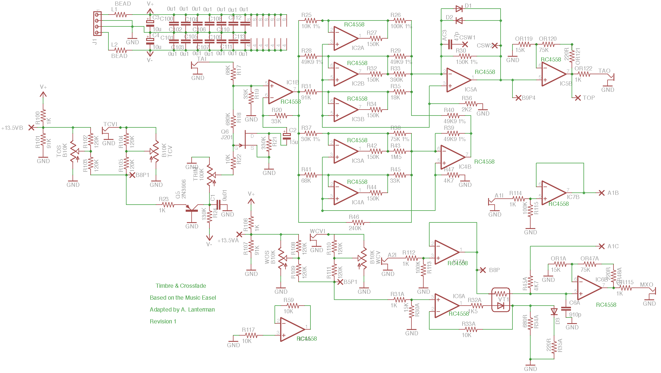
This is based on the timbre circuit on Board 9 and the single-vactrol
“waveshape” crossfade circuit on Borad 8 of the Music Easel.
You should spend some time studying the
original
schematics.
Warning: This board is designed to be highly flexible; it can be
configured in many different ways. Please read the notes below carefully
and decide what options you want before building.
Demo
(Note this video is of Version 0, so pay no attention to any mention I make
of errors on the PCB; those comments are not relevant to Revision 1.)
Schematic & layouts
Schematic
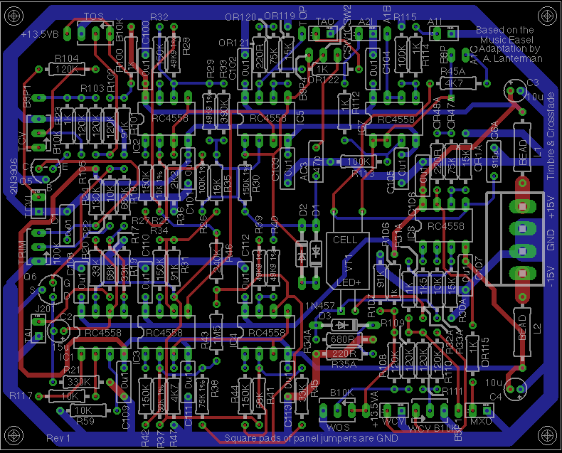
Complete PCB layout
PCB, silkscreen
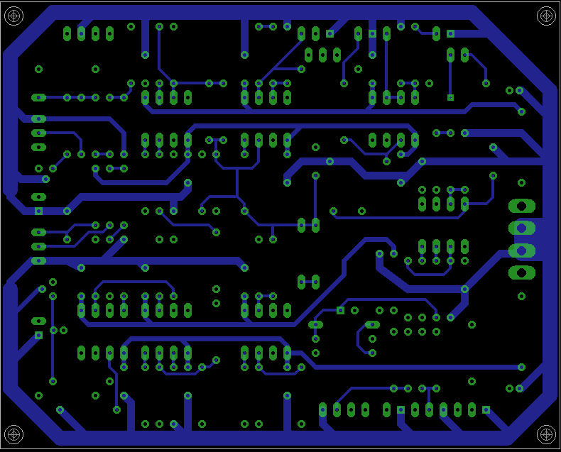
PCB, top copper layer
PCB, bottom copper layer
Notes
- I am convinced that the 50K sliders marked on the original schematics
(and this version of the board) should actually be 10K linear. The 120K
input and shaping resistors (R102, R103, R104, R105, R108, R109, R110,
and R110) are off-board in
the original Easel, but included on-board in this adaptation. - The original Easel has a 13.5 V supply, created using an op amp and a
transistor buffer. If you have such a supply, you may hook it to the two +13.5 pins
and omit R100, R101, R106, and R107.
Otherwise, leave the +13.5 pins unconnected and use R100, R101, R106, and R107,
which create “soft” +13.5 V supplies (via voltage dividers made by R100 with
R101, and R106 with R107.)
To counteract loading I found that lowering R100 and R106
from 10K to 1K is a good idea, so I marked these as 1K on the PCB. You
may want to experiment with other values. - The Q6 JFET is used as a variable resistor.
It is specified as a 2N4341 in the original, but it appears to be out of
production. I picked the J201
since it happened to come with the preinstalled Eagle libraries. I’ve tried
a MPF102 here too, and didn’t notice a difference.
R21 is marked as 6.8K on the original Buchla schematic.
I had to raise this value quite
a lot in order to not get too much gain through the VCA
with the offset knob at the lowest setting. I used 330K instead of
6.8K and marked R21 as such on the PCB. I recommend
that as a starting point if you’re using a J201 or MPF102 for Q6 (I tried both
and didn’t notice any difference). Your mileage may vary. Different values of
R21 (even instances of the same JFET model type)
may be appropriate for different choices of Q6. - I specified Q5 as a 2N3906 since
I happen to have of them and it also came
preinstalled in the Eagle libraries. In the original Music Easel schematic,
it is specified as a 2N4248, which seems to be out of production. You might
want to try other transistors here. - The circuit has been tested with RC4558s, which was deemed to be
electrically similar to the original RC4136s used in the Easel.
Other op amps will probably
work (many will probably work better!), but they have not been tried. - D3 is a 1N457.
I suspect a 1N4148s or a 1N914 will work, but I have not tested them. - D1 and D2 are not specified in the original schematic; I used 1N457s
here, but my suspicions in the previous bullet point apply here too.
Connections
Front panel connections usually have a square and round pad together in a
white box. The round pad is the signal, and the square pad provides a
convenient ground.
TAI – Timbre Audio Input
TAO – Timbre Audio Output
TCVI – Timbre CV input; amount of influence is controlled by setting of
TCV pot
WCVI – “Waveshape” crossfader CV input; amount of influence
is controlled by setting of WCV pot
A1I – Alternate input 1; buffered and appears at A1B
A1B – Buffered version of A1I input; may be used connected to A1C, or
not used at all, or connected to a switch
A1C – Corresponds to pin 10 of Board 8 of the original Easel schematics. It
corresponds to what you get by turning the waveshape control counterclockwise.
If you want to set this up like an original Easel, connect B9P4 or TOP directly
A1C, so turning the waveshape control counterclockwise corresponds to
the timbre circuit. If you want to always use the “waveshape” crossfader
as a stand alone crossfader, you can directly hook A1B to A1C. If you’d like
to switch between both options, hook A1C to the common terminal of a on-none-on
SPDT switch, and hook TOP or B9P4 to one “on” terminal and A1B to another
“on” terminal. (The issue of whether to use TOP or B9P4 is complex and
depends on how you set the resistors OR119, OR120, OR1A, and OR47A; see below.)
TOP – Timbre Output Pin – connected to A1C, or to a switch, or not used
(see options listed under the A1C description above). This is the timbre output
after the gain provided by IC5B (if gain is used).
B9P4 – Corresponds to Pin 4 of Board 9 of the original Music Easel –
connected to A1C, or to a switch, or not used
(see options listed under the A1C description above). This is the timbre
output before the gain provided by IC5B (assuming gain is used).
A2I – “Alternate” input 2; buffered and appears at B8P; used if creating a
stand-alone module. This corresponds to what you get when turning the
waveshape control clockwise.
B8P – Input to the Vactrol side of the “waveshape” crossfader. If you are
using the A2I input, you won’t need to use the B8P pad. If you are trying
to build an complete Easel, B8P corresponds to pin 12 of IC 4 on the
original
Easel Board 8 schematic. This is the pulse, square, or triangle shape
signal that you’d get by turning the waveshape control clockwise. If you
hook a signal directly to B8P, you should omit IC7, R112, R113, R114, R115
(notice this also takes out the A1I, A1B functionality, but that’s probably
OK since you’ll probably be directly hooked the timbre output to A1C
anyway). Most users building stand-alone modules will probably not need
to use B8P.
MXO – Mixed Output of the “waveshape” crossfader
CSW1, CSW2 – there’s a capacitor that provides some filtering action on the
timbre output. You can put a switch between CSW and CSW2 and experiment with
switching this cap in and out. If you want it to act like an original Easel,
just short CSW1 and CSW2.
Resistor options
- If you are using an op amp with some build in short-circuit protection,
like the specified RC4558s, then you can use the 220R resistors OR121 and
OR48A, and use wires instead of 1K resistors for OR115 and OR122. If, on the
other hand, you are using a different op amp capable of creating much bigger
currents, I recommend using wires instead of 220R resistors for OR121
and OR48A, and installing actual 1K protection resistors in the OR115
and OR122 spots. - OK, here is where things get really complicated. OR1A and OR47A
are specified as 15K and 75K; this is as things are in the original
Easel. This gives the raw timbre signal at B8P4 and whatever it is mixed with
at B8P a gain of 6. IC5B, OR119, OR120, OR121, and OR122 are not present
in the original Easel; this is a copy of the circuitry around IC6B to give
that gain of 6 at the TAO output. If you’d like your external signal input
at A2I to be subject to the same gain, then you can use 15K and 75K in
the OR1A and OR47A spots, respectively. However, you may prefer to
take the timbre output to mixer from the TOP pin, so it already has the
gain, in which case you can omit OR1A altogether, and use a wire for OR47A,
which turns IC6B into a unity gain buffer; in this case, IC5B boosts
the timbre output up to the level of typical signals, and will then be
on an even footing with most external signals, and IC6B won’t provide
additional undesired gain. Think carefully about your particular desired
gain structure.
Potentiometers
WOS – “Waveshape” croassfader Offset
WCV – “Waveshape” crossfader CV; controls amount of influence of the WCVI
input
TOS – Timbre Offset
TCV – Timbre CV; controls amount of influence of the TCVI
input
Disclaimer
These should be considered advanced projects, and should only be attempted
by people with extensive knowledge and experience in electronics,
particularly
in terms of practical construction and debugging techniques. The boards
are
dense and the documentation is sparse.
If you are just
getting started with Synth DIY, we recommend starting with kits
by Blacet Research or
PAiA, or boards by
Music
from Outer Space. (There are numerous other kit and
PCB manufacturers, but those are relatively newbie-friendly.)
If you try to build one of these projects, you must assume that you will be
on your own, and be confident enough to tackle the project under those
circumstances. I am interested in learning about people’s experiences
in building the boards, and will try to answer questions over e-mail,
but I don’t have time to do any hand holding.
Any PCBs made available to the public are provided as-is, with no
guarantees or warranties whatsoever. Similarly, no guarantees or warranties
are made about the correctness or usefulness of the information on these
webpages.
Any electronic project may present a risk of injury or
death, particularly when
dealing with mains voltages. It is important to follow appropriate safety
practices. The author of these
pages, Aaron Lanterman,
disclaims any liability for injury, death, or other damage caused in
using the PCBs or any of the information contained on these webpages.