
Music Easel Adaptation – Sequencer
Version 0
Original
circuit by
Don Buchla
(used with his kind permission);
adapted by Aaron Lanterman
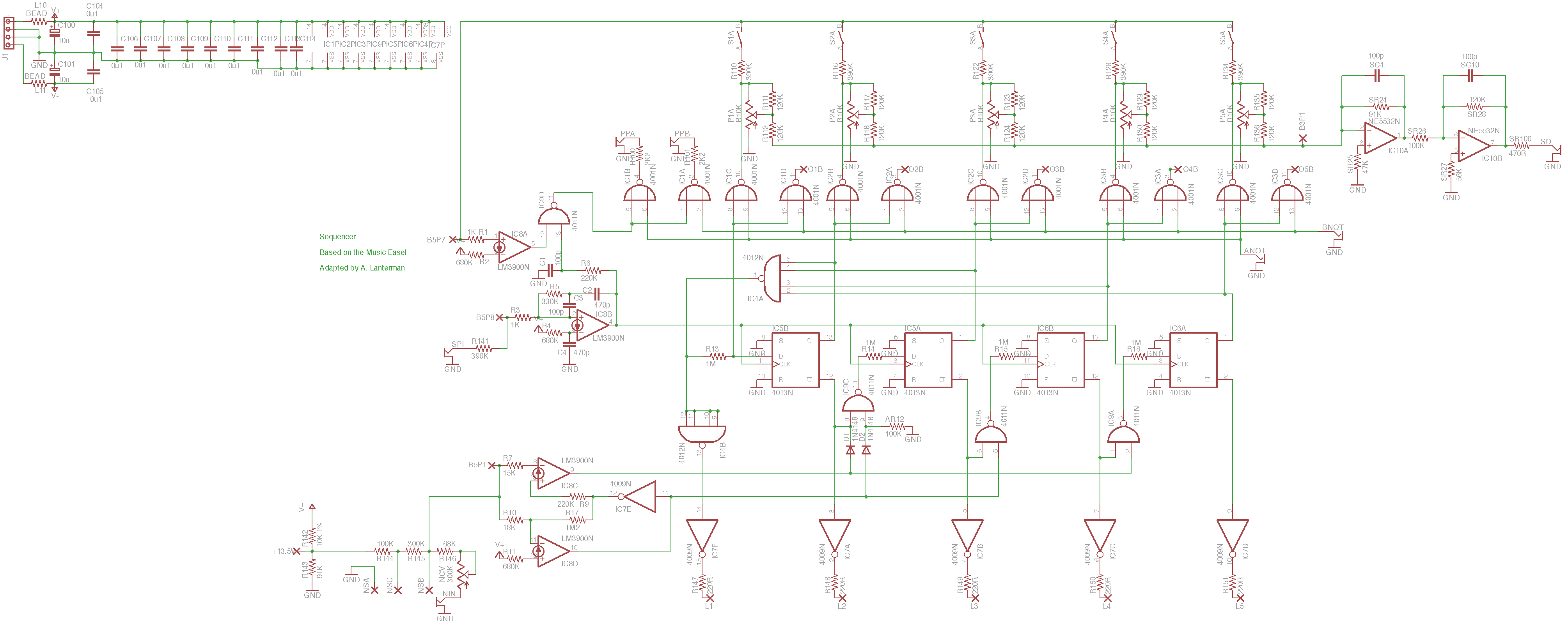
This is based on the sequencer circuit on Board 1 (along with the sequencer
summing circuitry on Board 3)
of the Music Easel.
You should spend some time studying the
original
schematics.
There are quite a few options in building this, depending on how you use
(or not) the “B” sequencer functions, which on the original Easel
correspond to the programmable card. This is one of the more complicated
adaptations I’ve done; read the information below carefully before
building.
<!–
Demo
–>
Schematic & layouts
Schematic
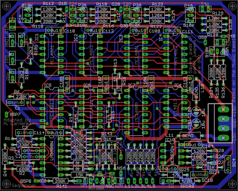
Complete PCB layout
PCB, silkscreen
PCB, top copper layer
PCB, bottom copper layer
Errors
- The op amps shown as NE5532s should be 4558s (I was just sloppy when
picking an op amp symbol). Actually a 5532 would probably work fine,
it would just be overkill. - The B5P1, B5P7, and B5P8 pins are mislabeled. They should
be B1P1, B1P7, and B1P8, respectively. - On the schematic and the PCB,
R144 and R145 are labeled as 100K and 300K,
respecively. On the original Easel schematic, these are actually 200K
resistors, which is probably what you should make them. I have a vague
recollection of changing the resistor values for some reason, but
I can’t recall what that reason was, so your best bet is probably to
assume that I was just confused.
Notes
- I am convinced that the 50K sliders marked on the original schematics
should actually be 10K linear. The 120K
input and shaping resistors (R111, R112, R117, R118, R123, R124, R129, R130,
R135, R136) are off-board in
the original Easel, but included on-board in this adaptation. - The original Easel has a 13.5 V supply, created using an op amp and a
transistor. If you have such a supply, you may hook it to the +13.5 pins
and omit R142 and R143.
Otherwise, leave the +13.5 pins unconnected and use R142
and R143, which create a “soft” +13.5 V supply.
You may need to change these resistors to counteract loading.
<!– - The circuit has been tested with RC4558s, which was deemed to be
electrically similar to the original RC4136s used in the Easel.
Other op amps will probably
work (many will probably work better!), but they have not been tried.
–> - D1 and D2 are not specified in the original schematic; I specified
1N4148s, but 1N457s are more likely, since they were used throught the
Easel. I doubt it matters much.
Connections
Front panel connections usually have a square and round pad together in a
white box. The round pad is the signal, and the square pad provides a
convenient ground.
SO – Sequencer CV output
B5P8 (mislabled, should be B1P8) – Corresponds to Pin 8 on the original
Easel Board 1 schematic; this is essentially the “sequencer pulse input”
(see SPI below). You can use this pin if you’re trying to make a Easel-style
programming card interface.
SPI – Sequencer Pulse Input; connects to Pin 8 on the original
Easel Board 1 schematic (B5P8 on the schematic, which should be labeled
B1P8) through a 390K resistor. This 390K resistor is off-board on the
Easel, but on-board this PCB adaptation. On the Easel, there’s a switch
that lets you select between “off,” the pulser output, and the keyboard
output. Of course if you’re making this into a module you can pulse it
with whatever you want. When pulsed, the sequencer advances to the
next stage.
NSA, NSB, NSC – connections for switch (needs to be a
single pole, center off type) to control the number of stages.
Connect the common of the switch to NSC, and connect the two other lugs
of the switch to NSA to NSB. The off setting is one of the three possibilites,
and the NSA and NSB sides are the other two. These settings should
correspond to chosing 3, 4, or 5 stages, but I’m not sure which is which.
NIN – CV input to modify the number of stages. This is run through a 300K pot,
NCV, which should theoretically control the amount of influence of NIN.
Frankly, don’t have the slightest clue how this will work in practice.
You may want to try a different pot value, or just ignore the NIN input
entirely, in which case just leave it disconnected.
L1 through L5 – light connections. The Easel schematic show the current
limiting resistors as being off board, between the lights and the power
supply. Here I put the current limiting
resistors on the card itself; I doubt it matters much which side of the
diodes they go on. You will want to connect pins L1 to L5 to the cathode
of the LEDs, and connect the anode to the power supply you want to use to
drive the LEDs. I listed the current limiting resistors
(R147 through R151) was 220 ohms. But that value appears to be assuming
a +5 V supply. There’s a variation which seems to use a +12 V supply and
680 ohm resistors, but that’s confusing to me since I don’t really see
anywhere on the main Easel schematics where +12 V is generated. In
any case, I use a +15 V supply to power the inverter chip,
so if you connect the LEDs to a +15 V supply, you will want to calculate
a new value for those resistors.
ANOT – Input for enabling the “A” sequencer outputs, which are
controlled by sliders P1A through P5B and mixed to form the sequencer output
at SO. Note that the logic of this input pin is “true low” style,
so to enable
the “A” outputs you need to set this pin to “logic 0,” i.e. ground, and
to disable the “A” outputs you need to set this pin to “logic 1,” typically
the positive supply rail.
This is connector pin 12 on Board 1 on the original
Easel schematics.
You may want to connect this input to a switch that
switches between +15 and ground, and label the +15 “on” and the ground
“off.” Or, if you want to leave the “A” sequencer permanently on,
just wire this to ground using the convenient square ground pin.
BNOT – Input for enabling the “B” sequencer outputs, which are associated with
to the sequencer outputs to the plug-in card slot on the original Easel.
Note that the logic of this input pin is “true low” style,
so to enable
the “B” outputs you need to set this pin to “logic 0,” i.e. ground, and
to disable the “B” outputs you need to set this pin to “logic 1,” typically
the positive supply rail.
This is connector pin 10 on Board 1 of the original
Easel schematics.
You may want to connect this input to a switch that
switches between +15 and ground, and label the +15 “on” and the ground
“off.” Or, if you want to leave the “A” sequencer permanently on,
just wire this to ground using the convenient square ground pin.
S1A through S5A – activation switches for sequencer stages 1 through 5
for the “A” sequencer.
O1B through O5B – These are the individual “B” sequencer outputs, which on the
original Easel would be sent to pins on the plug-in card. They correspond to
connector pins 6, 5, 4, 3, and 2 on Board 1 of the original Easel schematics.
The intention described by the Easel user’s manual is that the user would
select a resistor value for each ouput, and then tie the other ends of those
resistors fo B3P1, so that the currents would be summed along with the
currents generated by the sequencer “A” controls. The thinking behind the
setups of the “A” and “B” circuits is slightly different. In the case
of the sequencer “B” outputs,
the logical outputs of the NAND gates are at either 0
or 15 volts (or close to that), and the current is controled by the resistors
on the card, and these currents are fed to the virtual ground at B3P1, with
IC10A doing the summing, and IC10B inverting the signal since IC10A itself
is an inverting summer. In the case of the sequencer “A” outputs, the
“voltage-to-current” resistors R112, R118, R124, R130, and R136
are all the same value of 120K (unlike on the plug-in card, where they will
typically be different), and the current through these resistors is varyed
by varying the voltage at the wipers of potentiometers P1A through P5A.
You may want to completely ignore the O1B through O5B outputs and
just use the “A” part of the sequencer. Or you might want to make your own
sort of “card” that you can quickly swap resistors in and out. Or you
might want to replicate the structures with the potentiometers and the
two 120K resistors and create a second bank of slides for sequencer “B”,
and use the ANOT and BNOT inputs to activate or deactivate these
banks.
Also, if you do use the sequencer “B” outputs, you can choose to create
a totally separate summing circuit off-board (replicating IC10A and IC10B
and the surrounding resistors and capacitors) to create an entirely
separate summed sequencer output “B,” instead of bringing the sequencer
“B” outputs through the resistors into B3P1 and summing them along with
the sequencer “A” outputs.
B3P1 – Corresponds to Pin 1 on the original
Easel Board 3 schematic. You will only need this if you want to set up
Sequencer “B,” in which case you will either replicate the little
networks such as P5A, R135, and R136 (the pots with the 120K shaping and
input resistors), and hook them to the O1B through O1B outputs, and then
bring the 120K resistors together at the B3P1 virtual ground summing
node). Or instead of replicating the networks, you can used fixed
resistors like on an Easel programming card. See the “O1A through O5B”
description above.
PPA – Pulse output for Sequencer A; fires whenever Sequencer A is
enabled and the stage switch is set for a particular stage.
PPB – Pulse output for Sequencer B; fires whenever Sequencer B is
enabled and the stage switch is set for a particular stage. Note that
the “stage switch” might be hardwired, like on a Buchla programming
card, if desired. See the description of B1P7 (mislabeled as B5P7) below.
B5P7 (mislabeled, should be B1P7) – Corresponds to Pin 7 on the original
Easel Board 1 schematic. You will only need to use this if you’re going
to set up a Sequencer “B,” in which case you want to run the Sequencer “B”
outputs (O1B through O5B) through 390K resistors and switches (mirroring
the structure for Sequencer A such as, for instance, R110 and S1A),
summing all the switches at B5P7. Or, instead of using switches, you
may want to hard-wire these if you’re doing an Easel-style programming
card.
B5P1 (mislabeled, should be B1P1) – Corresponds to Pin 1 on the original
Easel Board 1 schematic. This is an input to the circuitry that
selects the number of stages. You proably won’t need this unless
you
are setting up an Easel-style programming card interface.
Potentiometers
NCV – Controls the amount of influence of the NIN input (theoretically).
You may want to try a value different than 300K. Or, if you aren’t going
to use the NIN input, just don’t bother to install this pot or R146.
Disclaimer
These should be considered advanced projects, and should only be attempted
by people with extensive knowledge and experience in electronics,
particularly
in terms of practical construction and debugging techniques. The boards
are
dense and the documentation is sparse.
If you are just
getting started with Synth DIY, we recommend starting with kits
by Blacet Research or
PAiA, or boards by
Music
from Outer Space. (There are numerous other kit and
PCB manufacturers, but those are relatively newbie-friendly.)
If you try to build one of these projects, you must assume that you will be
on your own, and be confident enough to tackle the project under those
circumstances. I am interested in learning about people’s experiences
in building the boards, and will try to answer questions over e-mail,
but I don’t have time to do any hand holding.
Any PCBs made available to the public are provided as-is, with no
guarantees or warranties whatsoever. Similarly, no guarantees or warranties
are made about the correctness or usefulness of the information on these
webpages.
Any electronic project may present a risk of injury or
death, particularly when
dealing with mains voltages. It is important to follow appropriate safety
practices. The author of these
pages, Aaron Lanterman,
disclaims any liability for injury, death, or other damage caused in
using the PCBs or any of the information contained on these webpages.