
Music Easel Adaptation – Balanced Modulator
Version 0
Original
circuit by
Don Buchla
(used with his kind permission);
adapted by Aaron Lanterman
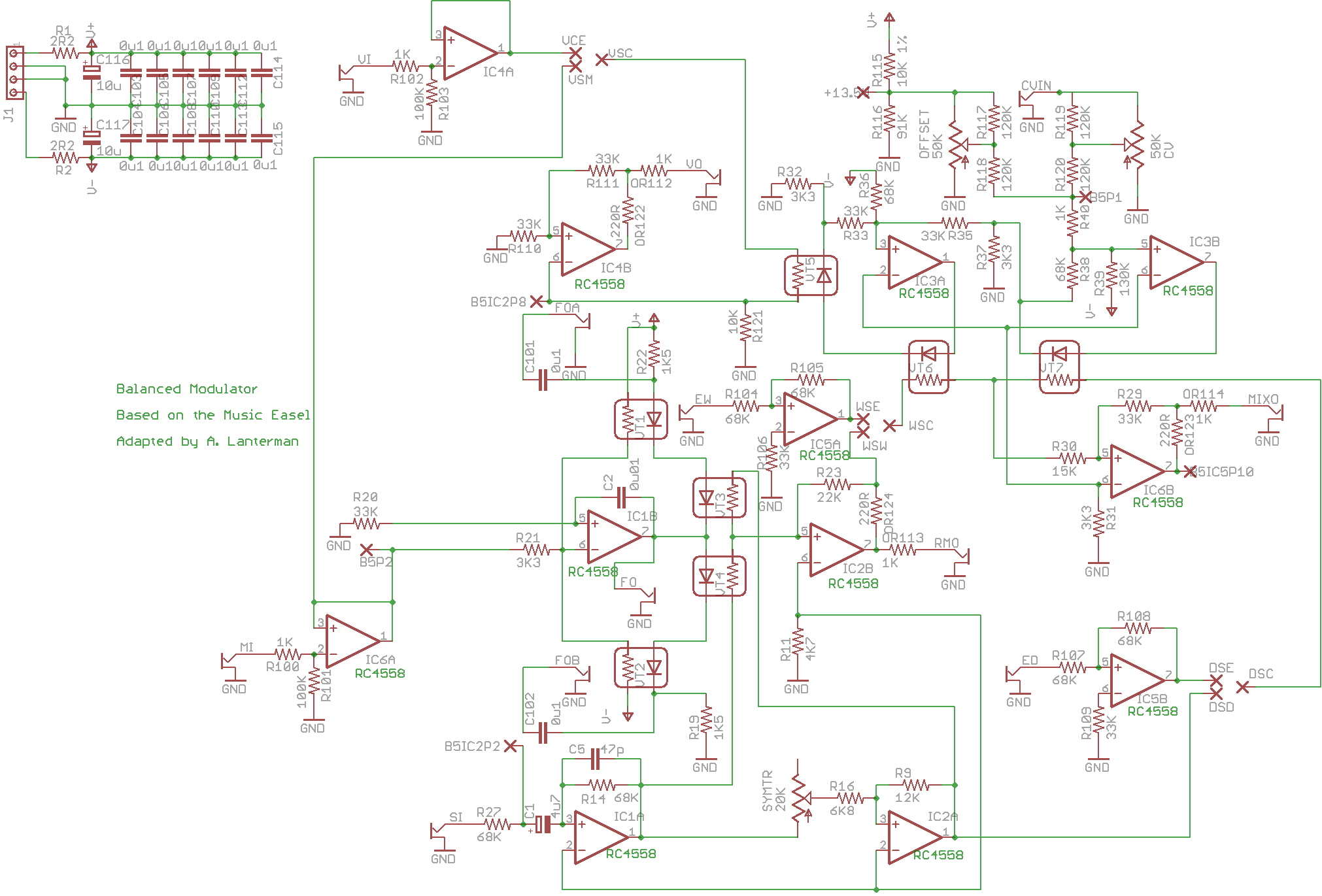
This is based on the balanced modulator circuit on Board 5 of the Music Easel.
You should spend some time studying the
original
schematics.
Warning: This board is designed to be highly flexible; it can be
configured in many different ways. Please read the notes below carefully
and decide what options you want before building.
Demos
Schematic & layouts
Schematic
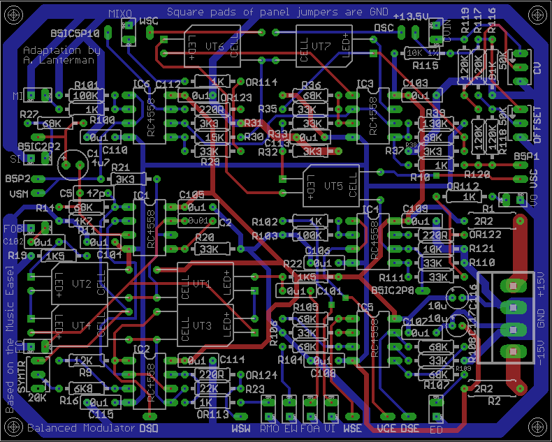
Complete PCB layout
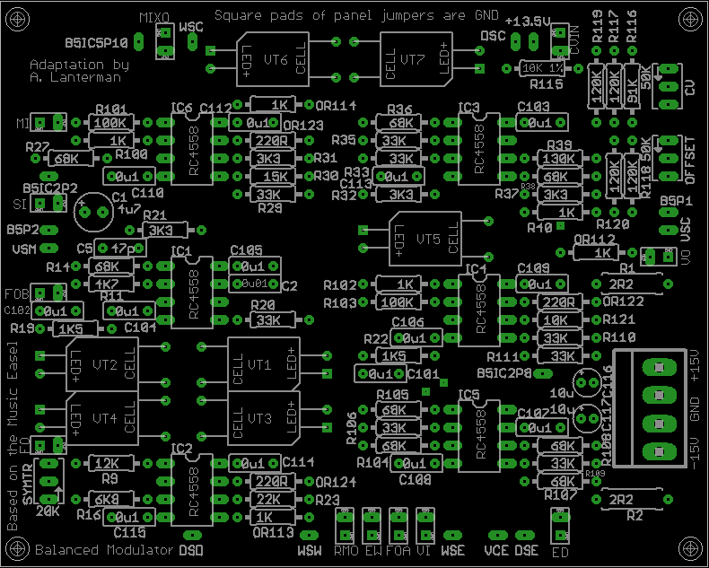
PCB, silkscreen
PCB, top copper layer
PCB, bottom copper layer
Errors
- The schematic and PCBs linked above contain
significant errors. The op amp inputs on EVERY op amp need to be swapped;
on every op amp IC
you need to swap pin 2 and
pin 3, and also pin 5 and pin 6, on every IC. - R115 and R116, are intended to create a
+13.5 volt supply.
On the original Easel, this is created on another
board with an op-amp and transistor buffer. Here it’s just a couple of
resistors, forming “soft” supply, so
to counteract loading I found that lowering R115 from 10K to 3.3K
is a good idea. - If you want to use the FO fuzz output, you should add a 0.1 microfarad
DC blocking cap, like the FOA and FOB outputs have. It should be pretty easy
to add this somewhere on the way between the board and the FO jack.
Notes
- I am convinced that the 50K sliders marked on the original schematics
(and this version of the board) should actually be 10K linear. The 120K
input and shaping resistors (R117, R118, R119, R120) are off-board in
the original Easel, but included on-board in this adaptation. - The original Easel has a 13.5 V supply, created using an op amp and a
transistor. If you have such a supply, you may hook it to the +13.5 pin
and omit R115 and R116.
Otherwise, leave the +13.5 pins unconnected and use R115
and R116, which create a “soft” +13.5 V supply. You may want to experiment
with changing these settings a bit, for instance lowering R115 and R116, to
counteract loading. - The circuit has been tested with RC4558s. Other op amps will probably
work (many will probably work better!), but they have not been tried. - I have a tradition
of specifying 2.2 ohm resistors (should probably be 1/2 watt)
at the power inputs
to perform power supply filtering along with 10 microfarad
electrolytics. I picked 2.2 ohms since this choice shows up on some Buchla
schematics; I did not pick it through any particularly scientific means. Any
low resistance should work here.
I actually use “ferrite beads,” as suggested by Ken Stone, and not resistors
in these spots.
Connections
Front panel connections usually have a square and round pad together in a
white box. The round pad is the signal, and the square pad provides a
convenient ground.
MI – Modulation Input
SI – Signal Input
EW, ED – External Wet, External Dry –
the balanced modulator has a crossfader that lets the
user fade between the “dry” signal input and the “wet” full ring mod signal.
These inputs let the user put in alternative “wet” and “dry” signals,
so the crossfader
may be used as a stand-alone submodule separate from the ring mod.
MIXO – Mixed Output of the crossfader – this is the actual output of the
“real Easel” balanced modulator
RMO – Ring Modulator Output – this is the pure ring mod signal.
FO, FOA, and FOB – fuzz outputs –
various highly distorted versions of the modulation input
signal. These taps were suggested by Grant Richter (who had many helpful
suggestions on this particular project.)
CVIN – crossfader CV input;
amount of influence is controlled by setting of CV pot
WSC, WSE, WSW – switch to select what goes in the “wet” side of the
crossfader, if you want this facility. Hook WSC to the common of an
on-none-on
single pole switch, and connect WSE (“external wet” select) and WSW (full ring
mod select) to the poles. If you don’t want this facility, and want it to act
like an original Easel, i.e. the crossfader is dedicated to the ring mod, then
simply hook WSW to WSC.
DSC, DSE, DSW – switch to select what goes in the “dry” side of the
crossfader, if you want this facility. Hook DSC to the common of an
on-(none)-on
single pole switch, and connect DSE (“external dry” select) and DSW (signal
input select)
to the poles. If you don’t want this facility, and want it to act
like an original Easel, i.e. the crossfader is dedicated to the ring mod, then
simply hook DSD to DSC.
(Note that if you take the “act like an original Easel” approach in the
last two paragraphs, you may omit IC5 and R104, R105, R106, R107, R108, and
R109. Also note that when external inputs are being used, the terms “wet”
and “dry” just denote different inputs – those external inputs can be whatever
you want.)
B5IC2P8, BIC2P2, BIC5P10 – these correspond to various points on the original
Easel schematic, if desired. The ICXPY notation refers to IC X (on the original
Easel schematic), pin Y (original Easel IC pins).
They might be useful to someone trying to clone a full Easel, but most
users will not need to use these.
VI – “variant input” – OK, this may get confusing (uhm, even more confusing,
I mean.) On the Easel, the control circuitry for the vactrols in the
crossfader for the ringmod drives an additional vactrol, which sort of forms
a VCA for the FM input for the principle oscillator. Here, I’ve set it up
as a stand-alone VCA that you can do whatever you want with.
VO – “variant output” – output of the VCA described above
VSC, VCE, VSM – switch to select what to send to the “variant” VCA. Connect
VSC to the common of an on-none-on single-pole switch, and connect VCE to
VSM to the poles. When switched to VCE, it will send the VI signal to the
VCA. When switched to VSM, it will send the modulation input (MI) to the VCA
(this is the “real Easel”) behavior. Of course, you can omit the switch and
just tie VSC directly to VSM or VCE, if you want to do such a thing.
Resistor options
- If you are using an op amp with some build in short-circuit protection,
like the specified RC4558s,
then you can use the 220R resistors OR122, OR123,
and OR124, and use wires instead of 1K resistors for OR112, OR113, OR114.
If, on the
other hand, you are using a different op amp capable of creating much bigger
currents, I recommend using wires instead of 220R resistors for OR122, OR123,
and OR124,
and installing actual 1K protection resistors in the OR112, OR113, OR114,
spots.
Potentiometers
offset – crossfader offset (Easel schematics and this version of
the PCB say 50K,
but I recommend 10K linear)
CV – crossfader CV; controls amount of influence of the WCVI
input (Easel
schematics and this version of the PCB say 50K, but I recommend 10K
linear)
SYMTR – I found the easiest way to trim this is to modulate an audio signal
with an LFO, and trim it until you get similar amplitude beats.
Disclaimer
These should be considered advanced projects, and should only be attempted
by people with extensive knowledge and experience in electronics,
particularly
in terms of practical construction and debugging techniques. The boards
are
dense and the documentation is sparse.
If you are just
getting started with Synth DIY, we recommend starting with kits
by Blacet Research or
PAiA, or boards by
Music
from Outer Space. (There are numerous other kit and
PCB manufacturers, but those are relatively newbie-friendly.)
If you try to build one of these projects, you must assume that you will be
on your own, and be confident enough to tackle the project under those
circumstances. I am interested in learning about people’s experiences
in building the boards, and will try to answer questions over e-mail,
but I don’t have time to do any hand holding.
Any PCBs made available to the public are provided as-is, with no
guarantees or warranties whatsoever. Similarly, no guarantees or warranties
are made about the correctness or usefulness of the information on these
webpages.
Any electronic project may present a risk of injury or
death, particularly when
dealing with mains voltages. It is important to follow appropriate safety
practices. The author of these
pages, Aaron Lanterman,
disclaims any liability for injury, death, or other damage caused in
using the PCBs or any of the information contained on these webpages.