
Music Easel Adaptation – Envelope Generator
Version 0
Version 0
Original
circuit by
Don Buchla
(used with his kind permission);
adapted by Aaron Lanterman
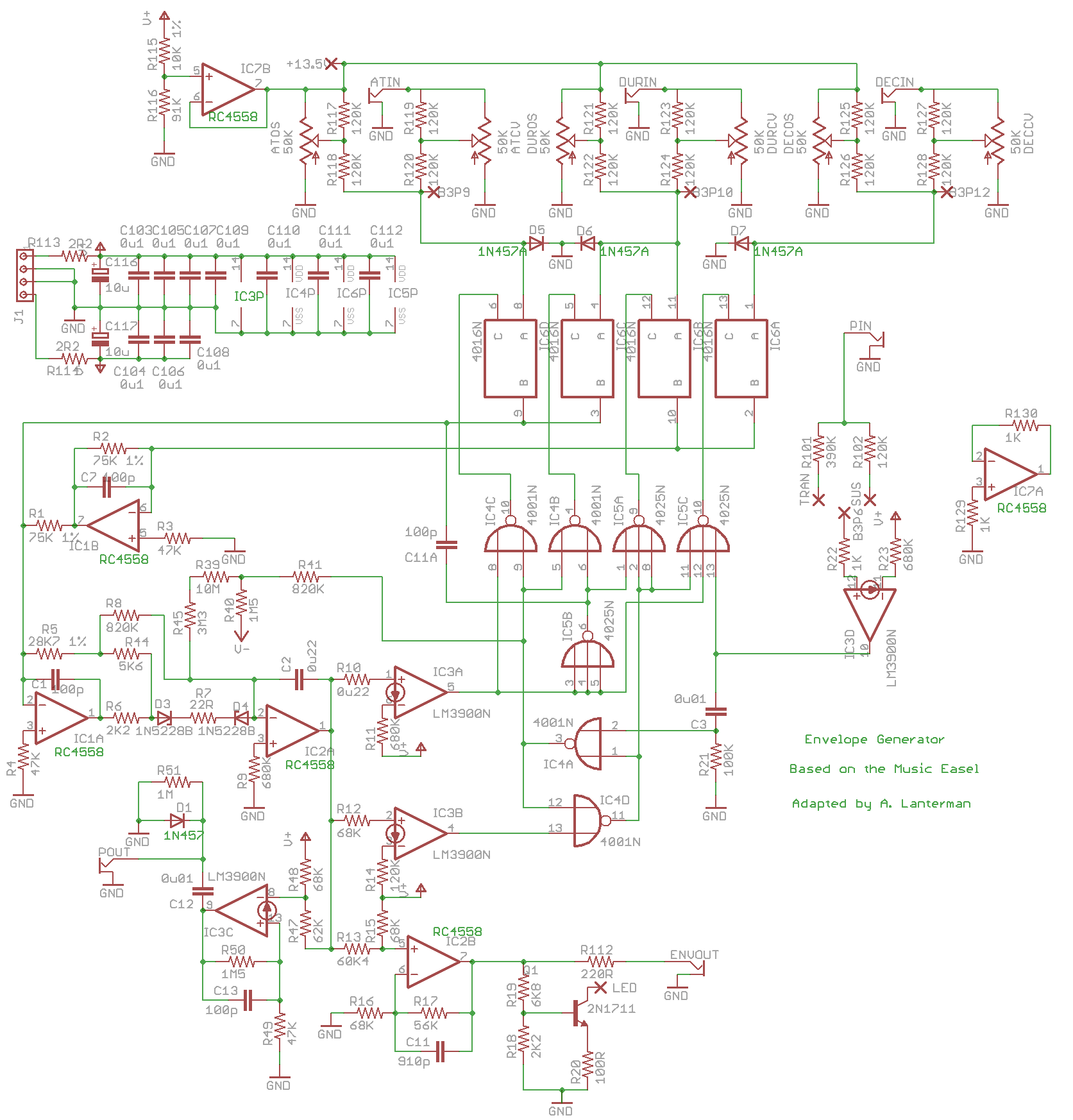
This is based on the envelope generator circuit of
Board 3 of the Music Easel.
You should spend some time studying the
original
schematics.
Demo
Schematic & layouts
Schematic
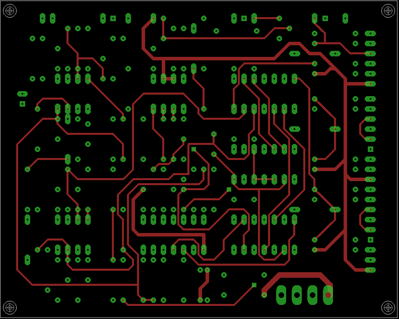
Complete PCB layout
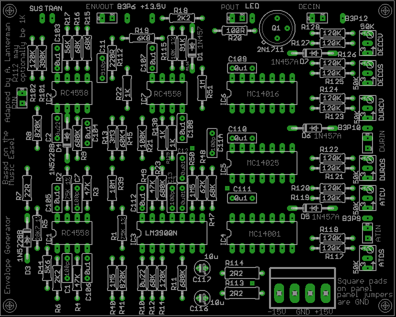
PCB, silkscreen
PCB, top copper layer
PCB, bottom copper layer
Errors
Surprisingly, and fortunately,
there are no errors on this board that require changing
connections or adding missing parts!
- R10 should be 68K, not 0u22 as labeled (obviously)
- I set some of the silkscreen text to the wrong laywer in Eagle, so it
didn’t appear. Missing text includes “D1 is 1N457,” “D5 through D7 are
1N457A,” “R112 may optionally be 1K.” The 8 pin chips are RC4558s, and
in the right column, from top to bottom, the chips are MC14016 (close
to the 2N1711 transistor), MC14025, and MC14001 (close to the power header).
Notes
- I am convinced that the 50K sliders marked on the original schematics
(and this version of the board) should actually be 10K linear. The 120K
input and shaping resistors (R117 through R128)
are off-board in the original Easel,
but included on-board in this adaptation. - The circuit has been tested with RC4558s, which was deemed to be
electrically similar to the original RC4136s used in the Easel.
Other op amps will probably
work (many will probably work better!), but they have not been tried. - Buchla went to the effort to specify 1N457 in one instance and
1N457A in another instance, so I’d be nervious about changing what dioes are
used. I’d be curious if to know if other diodes, such as 1N4148s or 1N914s,
will work. - I have a tradition
of specifying 2.2 ohm resistors (should probably be 1/2 watt)
at the power inputs
to perform power supply filtering along with 10 microfarad
electrolytics. I picked 2.2 ohms since this choice shows up on some Buchla
schematics; I did not pick it through any particularly scientific means. Any
low resistance should work here.
I actually use “ferrite beads,” as suggested by Ken Stone, and not resistors
in these spots. - Dan independently developed his own board for the Music Easel
Envelope Generator, and made some modifications to the circuit. I only
tested it in transient mode; I didn’t test it in sustain mode, and much
of Dan’s work addresses the sustain mode.
Here is a snippet
from an e-mail describing his work. I’m curious to see if other people
come across similar issues. - Bjorn wrote: “I am not sure whether a solution to get the transient function of the envelope generator with a regular gate signal has been proposed yet. Anyways, I have been able to get this functionality by replacing R101 with a 10nf cap.”
Connections
Front panel connections usually have a square and round pad together in a
white box. The round pad is the signal, and the square pad provides a
convenient ground.
ATIN, DURIN, DECIN – attack, duration, and decay CV inputs; influence is
controlled by ATCV, DURCV, and DECCV settings, respectively
PIN – pulse input
B3P6 – corresponds to original Easel Board 3, Pin 6
TRAN, SUS – connect TRANS and SUS to the extremes of a single-pole
on-none-on switch, and connect B3P6 to the common terminal of this switch.
This lets the user switch been “transient” and “sustained” modes. (Note
I only tested the transient functionality.)
POUT – pulse output
ENVOUT – envelope output
LED – on the Easel schematics, this is actually called “LAMP” and is
shown going through a lamp-looking symbol to a +12 V supply. I haven’t
tried doing anything with this, since it’s a low priority for me, but if
someone can get something to light up I’d love to hear about it.
+13.5 V – a supply created using a buffer op amp (most users will not need
this)
Potentiometers
The Easel schematics and this version of the PCB say these should be 50K,
but I recommend 10K linear.
ATOS, DUROS, DECOS – attack, duration, and decay offsets
ATCV, DURCV, DECCV – attack, duration, and decay CV controls; control
influence of ATIN, DURIN, and DECIN inputs, respectively
Disclaimer
These should be considered advanced projects, and should only be attempted
by people with extensive knowledge and experience in electronics,
particularly
in terms of practical construction and debugging techniques. The boards
are
dense and the documentation is sparse.
If you are just
getting started with Synth DIY, we recommend starting with kits
by Blacet Research or
PAiA, or boards by
Music
from Outer Space. (There are numerous other kit and
PCB manufacturers, but those are relatively newbie-friendly.)
If you try to build one of these projects, you must assume that you will be
on your own, and be confident enough to tackle the project under those
circumstances. I am interested in learning about people’s experiences
in building the boards, and will try to answer questions over e-mail,
but I don’t have time to do any hand holding.
Any PCBs made available to the public are provided as-is, with no
guarantees or warranties whatsoever. Similarly, no guarantees or warranties
are made about the correctness or usefulness of the information on these
webpages.
Any electronic project may present a risk of injury or
death, particularly when
dealing with mains voltages. It is important to follow appropriate safety
practices. The author of these
pages, Aaron Lanterman,
disclaims any liability for injury, death, or other damage caused in
using the PCBs or any of the information contained on these webpages.