
Music Easel Adaptation – Preamp & Envelope Detector
Version 0
Original
circuit by
Don Buchla (used with his kind permission);
adapted by Aaron Lanterman
This is based on the preamp and envelope detector circuit on Board 10 of
the Music Easel. You should spend some time studying the
original
schematic.
Schematic & layouts
Schematic
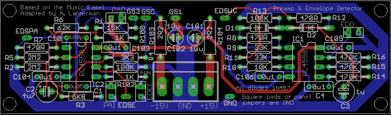
Complete PCB layout
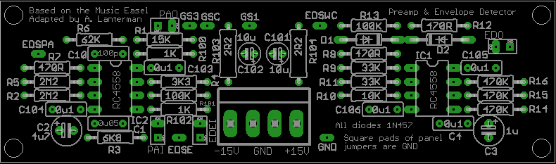
PCB, silkscreen
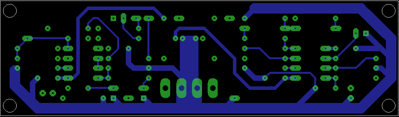
PCB, top copper layer
PCB, bottom copper layer
Notes:
- The circuit has been tested with RC4558s. Other op amps will probably
work (many will probably work better!), but they have not been tried. - R100 is an optional resistor. It is not present in the original
circuit. R7, a 470 ohm resistor in the feedback path of the original provides
some short circuit protection that relies on specific short circuit protection
built into the RC4558, which may be missing from other op amps. If you are
using another op amp without such built-in protection, particularly ones
capable of generating a lot of current, we recommend installing R100, a 1K
short circuit protection resistor. If you are using RC4558s, you can replace
R100 with a wire, or include it (I actually accidentally built my prototype
with this 1K in place even though I was using RC4558s.) - The diodes in the original are 1N457s.
I suspect 1N4148s or 1N914s will work, but I have not tested them. - I have a tradition
of specifying 2.2 ohm resistors (should probably be 1/2 watt)
at the power inputs
to perform power supply filtering along with 10 microfarad
electrolytics. I picked 2.2 ohms since this choice shows up on some Buchla
schematics; I did not pick it through any particularly scientific means. Any
low resistance should work here.
I actually use “ferrite beads,” as suggested by Ken Stone, and not resistors
in these spots.
Connections
Front panel connections usually have a square and round pad together in a
white box. The round pad is the signal, and the square pad provides a
convenient ground.
GS1, GSC, GS3 – Gain setting switch connections.
Use a SPDT on-off-on switch.
Hook GSC to the common connection, and GS1 and GS3 to the on connections.
When the switch is in the “off” position that corresponds to “gain setting 2.”
PAI – Preamp input (recommend using a normalled jack such that the normalled
connection goes to ground, or else you’ll pick up hum when nothing is plugged
in; might also recommend using shielded coax, but it’s not essential)
PAO – Preamp output
EDO – Envelope detector output
EDEI – Optional external input for envelope detector; gets buffered and
sent to EDSE
EDSE – Envelope detector switch – external input option
EDSPA – Envelope detector switch – preamp option
EDSC – Envelope detector switch – common connection
Options:
- If
you want to rig this like the original Easel, such that the preamp output
is always routed to the envelope detector input, then ignore EDEI and EDSE
and connect EDSPA directly to EDSC. - If you would like to be able to switch between using the preamped signal
and an external signal to drive the envelope detector (in the latter case
the PA and ED act separately), then use a SPDT on-none-on switch with EDSC
as the middle connection and EDSE and EDSPA as the on connections. (Another
possibility is to perform this switching function using a normalled jack,
such that the PA ESDPA is routed to EDSC when the jack isn’t used, and
ESDPA is overriden by ESDE when something is plugged in.)
GND – A random ground connection if you need it. I can’t remember why I
put it there.
Disclaimer
These should be considered advanced projects, and should only be attempted
by people with extensive knowledge and experience in electronics,
particularly
in terms of practical construction and debugging techniques. The boards
are
dense and the documentation is sparse.
If you are just
getting started with Synth DIY, we recommend starting with kits
by Blacet Research or
PAiA, or boards by
Music
from Outer Space. (There are numerous other kit and
PCB manufacturers, but those are relatively newbie-friendly.)
If you try to build one of these projects, you must assume that you will be
on your own, and be confident enough to tackle the project under those
circumstances. I am interested in learning about people’s experiences
in building the boards, and will try to answer questions over e-mail,
but I don’t have time to do any hand holding.
Any PCBs made available to the public are provided as-is, with no
guarantees or warranties whatsoever. Similarly, no guarantees or warranties
are made about the correctness or usefulness of the information on these
webpages.
Any electronic project may present a risk of injury or
death, particularly when
dealing with mains voltages. It is important to follow appropriate safety
practices. The author of these
pages, Aaron Lanterman,
disclaims any liability for injury, death, or other damage caused in
using the PCBs or any of the information contained on these webpages.