
Music Easel Adaptation – Pulser & Inverter
Version 0
Original
circuit by
Don Buchla
(used with his kind permission);
adapted by Aaron Lanterman
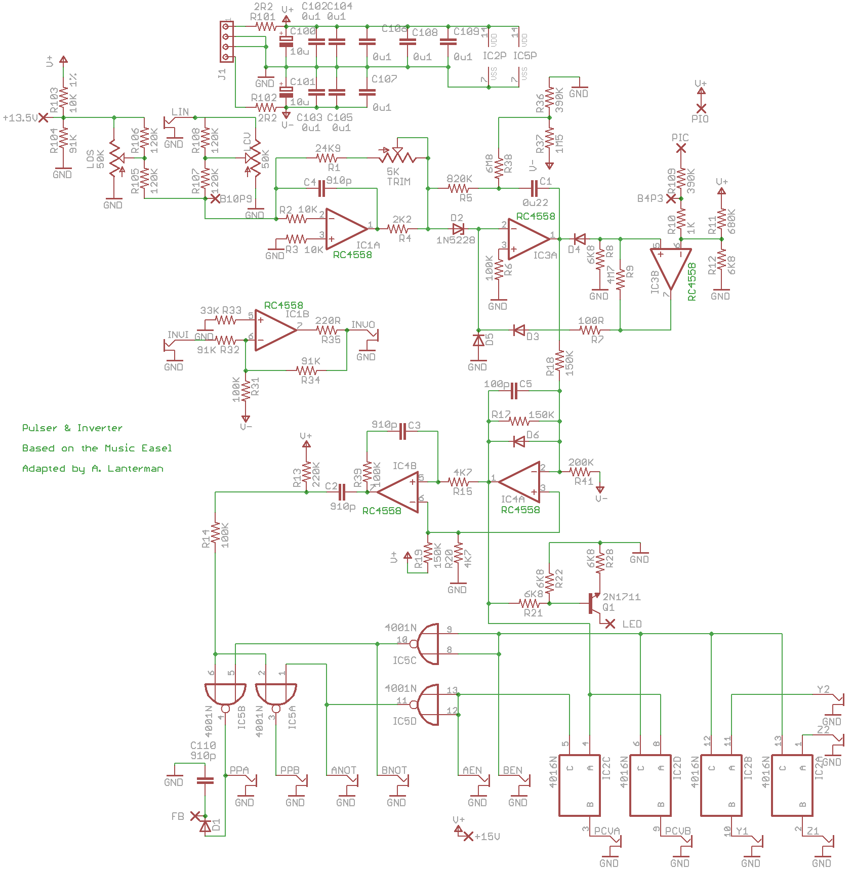
This is based on the pulser & inverter circuits on Board
of the Music Easel
You should spend some time studying the
original
schematics.
Demo
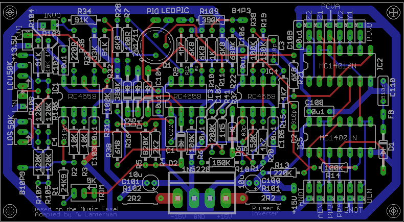
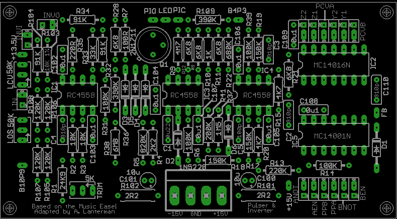
Schematic & layouts
Schematic
Complete PCB layout
PCB, silkscreen
PCB, top copper layer
PCB, bottom copper layer
Errors
The schematic and PCBs linked above contain some significant errors, most of
which must be
corrected during construction.
- R10 on the schematic and board is shown as going to pin 6 of IC3B,
the negative terminal. This is catastrophically incorrect;
R10 should connect to pin 5, the
positive terminal, instead.
The easiest way to do this is to omit R10
from its usual spot, and include it as a
jumping resistor running from B4P3 to pin 5 of IC3. - You must add jumper to connect the junction of R5, R38, and C1 with
pin 2 of
IC3A (which also connects with D2).
I found the easiest way to do this is to solder a little tiny
jumper between D2 (side near IC3) and C1 (side near IC3). Now that you know
this change is coming, you can probably easily accommodate it by cleverly
bending some leads over while stuffing and soldering.
(If you don’t do this, the op amp is not operating in proper feedback mode and you’ll get a “thresold” effect when
turning the offset control.) - R103 and R104 are intended to create a +13.5 volt supply.
On the original Easel, this is created on another
board with an op-amp and transistor buffer. Here it’s just a couple of
resistors, forming “soft” supply, so
to counteract loading I found that lowering R103
from 10K to 3.3K is a good idea.
- LOS and LCV should be 10K linear, not 50K.
- I set some of the silkscreen text to the wrong layer in Eagle, so it
didn’t appear. Somewhere on the board it should say “Adapted by A. Lanterman,”
“Pulser & Inverter,” and “Based on the Music Easel,” and it should also say
something about D3-D6 being 1N457s.
Notes
- I am convinced that the 50K sliders marked on the original schematics
(and this version of the board) should actually be 10K linear. The 120K
input and shaping resistors (R105, R106, R107, and R108) are off-board in
the original Easel, but included on-board in this adaptation. - The original Easel has a 13.5 V supply, created using an op amp and a
transistor. If you have such a supply, you may hook it to the +13.5 pin
and omit R103 and R104.
Otherwise, leave the +13.5 pins unconnected and use R103
and R104, which create a “soft” +13.5 V supply. I found it important to lower
R100 and R106 to something like 3.3K to counteract loading. - The circuit has been tested with RC4558s, which was deemed to be
electrically similar to the original RC4136s used in the Easel.
Other op amps will probably
work (many will probably work better!), but they have not been tried. - D3-D6 are 1N457s.
I suspect a 1N4148s or a 1N914 will work, but I have not tested them. - I have a tradition
of specifying 2.2 ohm resistors (should probably be 1/2 watt)
at the power inputs
to perform power supply filtering along with 10 microfarad
electrolytics. I picked 2.2 ohms since this choice shows up on some Buchla
schematics; I did not pick it through any particularly scientific means. Any
low resistance should work here.
I actually use “ferrite beads,” as suggested by Ken Stone, and not resistors
in these spots.
Connections
Front panel connections usually have a square and round pad together in a
white box. The round pad is the signal, and the square pad provides a
convenient ground.
PIC, PIO, FB – Pulse Input Common, Pulse Input One-Shot, and Feedback. You
want to try to find a single-pole on-off-(on) switch, where the (on) indicates
momentary operation. Hook PIC to the common switch terminal, hook PIO to
the (on) terminal, and hook FB to the regular on terminal. This will let you
do just one “pulse,” or if you switch to the feedback mode quickly after
doing one pulse, the
pulser will drive itself and you will get repeated pulses. The middle position
turns off the pulsing. If need be, you could just use a regular on-off-on
switch here.
PCVA, PCVB – Pulser CV outputs A and B. A is active when AEN is set high; B
is active when BEN is set high.
PPA, PPB – Pulser pulse outputs A and B. A is active when AEN is set high; B
is active when BEN is set high.
Y1, Y2 – terminal of an electronic switch; connection made when BEN
is set high (untested)
Z1, Z2 – terminals of an electronic switch; connection made when BEN is
set high
ANOT, BNOT – logical “not” of AEN and BEN
AEN, BEN – A and B enables; see other connection instructions for details of
what they enable. I plan to connect these to a switch that will let be switch
between automatically-on (connect to +15 V) and connect to an external input.
Most users will probably just want to tie AEN to +15 so the A outputs are
always enabled. Some users may want to just ignore the B outputs entirely.
Some might want to only use the “B” part of the circuit to control the
Z1,Z2 and Y1,Y2 electronic sswitches, and ignore the pulser B outputs. Do
whatever makes you happy.
INVI, INVO – inverter input and output; takes 0-10 V CV and outputs 10-0 V
CV. The inverter is independent of the rest of the pulser, so you can invert
whatever CV signals you want.
LED – on the Easel schematics, this is actually called “LAMP” and is
shown going through a lamp-looking symbol to a +12 V supply. I haven’t
tried doing anything with this, since it’s a low priority for me, but if
someone can get something to light up I’d love to hear about it.
Potentiometers
LOS – Level (pulser rate) Offset (Easel schematics and this version of
the PCB say 50K,
but I recommend 10K linear)
LCV – Level (pulser rate) CV; controls amount of influence of the LIN
input (Easel
schematics and this version of the PCB say 50K, but I recommend 10K
linear)
TRIM – Trims the pulser rate – set to personal taste
Disclaimer
These should be considered advanced projects, and should only be attempted
by people with extensive knowledge and experience in electronics,
particularly
in terms of practical construction and debugging techniques. The boards
are
dense and the documentation is sparse.
If you are just
getting started with Synth DIY, we recommend starting with kits
by Blacet Research or
PAiA, or boards by
Music
from Outer Space. (There are numerous other kit and
PCB manufacturers, but those are relatively newbie-friendly.)
If you try to build one of these projects, you must assume that you will be
on your own, and be confident enough to tackle the project under those
circumstances. I am interested in learning about people’s experiences
in building the boards, and will try to answer questions over e-mail,
but I don’t have time to do any hand holding.
Any PCBs made available to the public are provided as-is, with no
guarantees or warranties whatsoever. Similarly, no guarantees or warranties
are made about the correctness or usefulness of the information on these
webpages.
Any electronic project may present a risk of injury or
death, particularly when
dealing with mains voltages. It is important to follow appropriate safety
practices. The author of these
pages, Aaron Lanterman,
disclaims any liability for injury, death, or other damage caused in
using the PCBs or any of the information contained on these webpages.