
Buchla Music Easel Slider Analysis
There’s some confusion over whether the sliders in the Buchla Music Easel
should be linear or logarithmic.
Mark Verbos said that the ones in the Easels he’s seen have been logarithmic,
and the assembly instructions say they are logarithmic. Luther says the
ones his his Easel are linear.
The sliders in the Easel have their tops hooked to +13.5 V (which I’m
generically calling V_EN in the notes below). The wiper is connected
to the modules through a 120K resistor, which I’m generically calling R_in,
and the wiper is also connected to the V_EN supply, which I’m calling R_sh
(for “shaping”). I am calling these R_card.
The Easel also has a plug in card that the user puts resistors into. The
resistors connect the V_EN supply to the module inputs.
The Easel sliders have “1” through “10” settings, and the back of the Easel
manual lists card resistor values that correspond with these setting.
One clue as to the designer’s intent is that the “1” thourgh “10” level
settings are specifically called “Conductance Values” in the table in the Easel
manual. Indeed, if you plot the level settings vs. reciprocal resistance,
you get a straight line (slighly off in a few places, I assume due to
rounding desired resistances to nearest easily available resistance values).
Assuming the card input is held at a fixed voltage
via an op amp feedback loop, this means the input current is a linear function
of the level setting (the blue line below, assuming the input is at ground.)
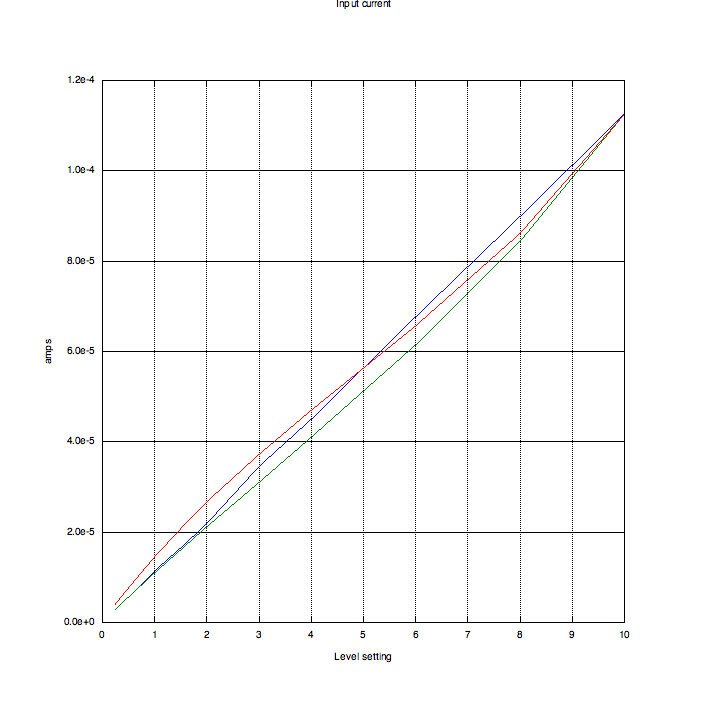
Again assuming an input held at ground, a linear slider (assuming equally
spaced tick marks) gives us the red line, which centers nicely on the blue
line – in fact, at level setting 5, they are identical. Higher levels dip
a little lower, and lower levels rise a little higher.
If we set R_sh to a “near infinite” value, essentially taking it out of the
circuit, we get the green line, which consistently dips below the blue line.
From this we can suppose that R_sh is intended to balance the loading
of R_in.
Here’s my handwritten analysis:
page 1,
page 2.
Here is my FreeMat code
(should work in MATLAB and Octave) used to make these plots. You’ll notice
there’s some other experiments I commented out. I couldn’t find a particular
equation relating travel to resistance for logarithmic pots, so I guessed one
using a base I could vary. Any log pot I put in created a line that drooped
well below the blue line. It might be possible to counteract some of
the droop by lowering the value of R_sh, but I didn’t try that. I also tried
to read pixel locations off a photograph of the Easel front panel to take
into account that the pixels on the front panel aren’t evenly spaced. This
resulted in a curve that was a little higher than the red line at the lower end
and a little lower at the upper end. I suspect maybe the original sliders,
if they are linear, aren’t quite as linear near the ends, so maybe the varying
tick marks account for that. In any case, I cannot counteract the effect
of using a log slider by using the tick marks.
The upshot is that if the assembly manual says to use logarithmic sliders,
I can’t argue with that, but I cannot reconcile that with the resistor values
given in the Easel manual – which fit so nicely assuming a linear pot.
If anyone can provide an analysis in which log pots make sense, I’d love
to see it!
Aaron Lanterman
Last updated 6/3/09