
ECE4803B: Theory and Design of Music Synthesizers
Spring 2006
Homework #6
Due: Wednesday, April 5th at the start of class
Ground rules on this homework: You may verbally
discuss approaches to the
problems with each other while looking at the schematics, and
are encouraged to do so; but you
may not look at each other’s written
solutions or ask “what did you get on
part XYZ of problem ABC.” (In future homeworks, I will allow
varying degrees of
explicit collaboration on certain problems.)
Below, I will use underscores to indicate subscripting.
Problem 1
What is the “cutoff” frequency (i.e. the omega_c from lecture)
of Rene
Schmitz’s MS-20 clone as a function of the current
at the control pin of the CA3080s? (You should be able to do this
by just using the formula for omega_c for the Sallen-Key in terms of
the gains and capacitors; just include the gain of the resistive
divider at the input of the OTA together with the gain of the OTA.)
Problem 2
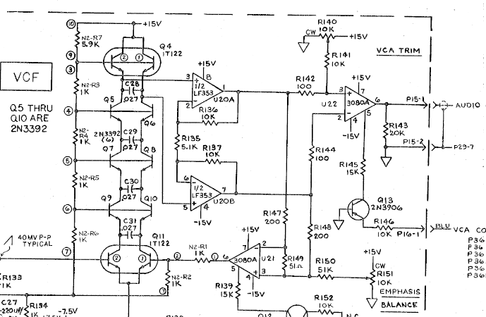
Pick one of the state-variable VCF schematics below based on on the
second-to-last
digit of your GTID number.
a) Are the variable-gain integrator stages inverting or non-inverting?
(Be sure to consider the combined
effect of both the OTA and the op-amp,
if an op-amp is being used as an integrator.)
b) What is the “cutoff” frequency as a function of the current at the
control pins of the OTAs? (Again, just include the gain of the resistive
divider at the input of the OTAs together with the gain of the OTA and you
should be all set.)
0-3)
Oberheim SEM VCF – you want to look at the page that says “VCF.”
4-6)
ASM-1 VCF – ignore the 30 pF caps.
7-9) PAiA
9730 VCF – either Filter A or Filter B (they have
the same integrator structure.)
Problem 3
Choose a schematic below based on the second-to-last digit of your GTID number.
The patented Moog transistor ladder VCF contains a cascade of four
one-pole lowpass filter sections. Find the cutoff frequency of
one of those sections as a function of the control current
being pulled from the tied emitters of the transistor pair that feeds
the ladder. Two things to note: 1) Notice that when analyzing the Moog
VCF, we don’t include a
resistive divider in the gain as we’ve done in other VCF cutoff computations;
there is a resistive divider right at
the first input, but it’s not important for our frequency analysis. 2)
I wrote expressions on the board for a one-sided ladder; for a real
Moog two-sided ladder, the control current gets split between the two
halves of the ladder, so you get a transconductance gain from each
transistor pair that’s like that of an OTA, and the formula for the
cutoff is basically the same as for the OTA-C filters we looked at
earlier (except we leave out the resistive divider).
If you don’t see a specific unit on a capacitor, there’s usually an implied
“microfarads.”
0) Monowave
VCF – The Monowave was designed by
Paul Maddox,
a synth DIYer who hand-built
and sold 25 as a limited edition; he’s now declared
the project “hardware open source.” See the whole thing
here!
1) Oberheim OB-Mx
– Strangely, Tom Oberheim had nothing to
do with this synth; Gibson had bought the rights to the Oberheim name.
Don Buchla was called in to try to save the project, but it eventually
wound up released before it was really ready against Buchla’s wishes.)
2) Minimoog VCF
3) Moog Modular 904A VCF – assume the “Range 1” capacitor
is switched in (notice the ladder is drawn “sideways,” at the bottom of
the page)
4) Moog Modular 904A VCF – assume the “Range 2” capacitor
is switched in
5) Moog Modular 904A VCF – assume the “Range 3” capacitor
is switched in
6) Moog Rogue (see last page for schematic)
7) Moog Prodigy (see last page for schematic)
8) Moog
Source
9) Memorymoog (this is a reduced snippet
of a much larger scan, Sheet1.tif, found
here).