
ECE4893A: Electronics for Music Synthesis
Spring 2011
Homework #4
Due: Friday, April 22, by 3:00 PM
This homework will be graded out of 100 points.
Turn-in procedure:
We will not have our usual lecture, on either the 22nd or the 25th.
If you happen see me, you can give it to me in person; otherwise, just slip
it under my Van Leer 276 office door. I will collect them from my
office around 3:00ish PM on Friday. If you turn it in after that time, or
if you turn it in before that Friday, please e-mail me to let me know
so I can be sure to come in and collect it.
Ground rules: You are free to discuss approaches to
the problems with your fellow students, and talk
over issues when looking at schematics,
but your solutions should be your own. In particular, you should never
be looking
at another student’s solutions at the moment
you are putting pen to paper on your
own solution. That’s called “copying,” and it is lame.
Unpleasantness,
including referral to the Dean of Students for investigation,
may result from such behavior.
In particular, the use
of “backfiles” of solutions from homeworks and quizzes assigned in
previous offerings of this course is strictly prohibited.
Late penalty: If you turn it in late by
Monday, April 25, by 3:00 PM, I will still grade it, but I will
take off 30 points. This isn’t to be mean – it’s
to encourage you to get it turned in
and move on to whatever other work you have to do in other classes,
even if it’s not perfect – but also to encourage you to go ahead
and do the work and turn it in and learn some stuff and get some
points, even if you’re past the deadline.
Problem 1
In this problem,
we’ll
look at the
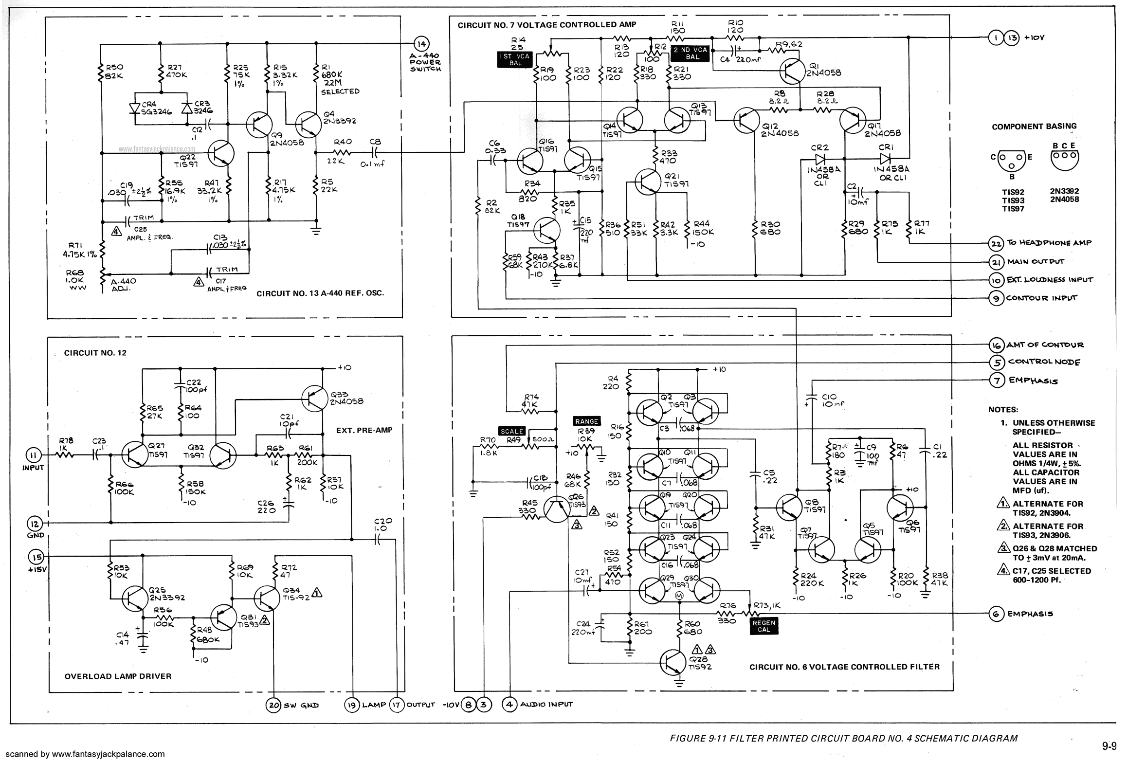
VCF in the Minimoog (at least the
version linked here; the Minimoog went through several revisions). The
scan I am linking to was posted by someone calling themselves
Fantasy
Jack Palance; this FJP person has
posted
a
lot more info about it, including the story about how
they acquired their Minimoog.
If you don’t see a specific unit on a capacitor, there’s usually an implied
“microfarads.”
a) The Moog transistor ladder VCF contains a cascade of four
one-pole lowpass filter sections. In class, I presented an analysis of a
hypothetical
“one-sided” latter
to get a feel for how this kind of circuit works. The analysis
of the actual “two-sided ladder” is a bit more complicated. We’ll rely on
the analysis in Tim Stinchcombe’s
Analysis
of the Moog Transistor Ladder and Derivative Filters, particularly
Equation 13 on page 11. Using this formula,
find the cutoff frequency (in Hertz) of
one of those sections in the Minimoog’s transistor ladder
as a function of the control current
being pulled from the tied emitters of the transistor pair that feeds
the ladder.
(Note that when analyzing the Moog VCF, we don’t include a
resistive divider in the gain as we’ve done in OTA-C filter
cutoff computations;
there is typically a resistive divider right at
the first input, but it’s not important for our frequency analysis.)
b) Let’s do some DC analysis.
At DC, the caps are open circuits.
For the purpose of this analysis, ignore R76 (the 330 ohm resistor) and
the R73 (the 1K regeneration calibration pot); treat them as “open” too.
Supposing that the transistors draw negligible
current through the bases, what are the voltages
at the bases of the four stages of the
ladder? (Number the stages 1 through 4, from bottom to top).
Problem 2
Let’s check out the
ASM-1
State Variable VCF. For the purpose of this analysis, ignore (i.e. “open”)
the 30 pF caps C1 and C3.
You should
be able to find the OTAs that are taking the place of resistors in the
variable gain integrators.
You should also be able to find the capacitors
that the output currents of the OTAs are being sent into, as well as
the op amps that buffer the resulting voltages.
Finally, you should be able
to look at the inputs of the OTA and find what resistor you will want to
call “Rbig” and what resistor you will want to call “Rsmall” to form the
Rsmall/Rbig gain factor that you will want to combine with the gain of
the OTA when computing the critical frequency f_0. (I might have called
this f_c in lecture).
Real OTAs have some non-ideal offset; P2 and P3 are trim pots that can help
compensate for this offset. We will assume the OTAs are ideal so you can
assume the positive inputs of the OTAs are grounded.
a) Are the variable-gain integrators forming this SVF
inverting or non-inverting?
b) Find
f_0 as a function of the current fed to the control current inputs
of the OTAs. This should be a simple calculation once you find the component
values you need.
c) If R16 was increased, would the Q of this filter increase or decrease?
Briefly explain your reasoning.
Problem 3
Let’s take a look at
Tom Gamble’s EFM VCF8E circuit, which is somewhat based on
the Korg MS-20 (but notice the capacitor values are somewhat different).
(Tom appears to have taken down the schematic on his ele4music.com site,
but it was kindly archived by fonik).
It has two
separate filter circuits, but they look more or less the same to me.
a) When switched in the lowpass mode, find the OTA control current
that would
result in a critical frequency f_0
(in some lectures I called this f_c) of 2500 Hz.
(The 10K resistors to the negative supply at
the output of the buffers are just goo needed to make the built-in
Darlington buffers of the LM13700 work.) Remember you can fold the
R_small/R_big factor in with the gain of the OTA when using the formula
for the critical frequency of a Sallen-Key filter. Because the two capacitor
values are the same and the resistor values are the same, this is a
relatively simple calculation.
b) In the original Korg MS-20, resonance is controlled with a pot. Notice
how Tom has modified the circuit to make the resonance voltage controllable.
In class, we showed that for this “Bach” topology, a feedback of K < 2 is
needed, or else the filter will go unstable. What value of control current
for the resonance-controlling OTA would give a feedback of 2? (I conjecture
that
Tom has designed this so that isn't possible, but I haven't checked it
in detail.)
Problem 4
In class, we briefly looked at the
Buchla 292C Lowpass Gate. The lowpass gate is basically
a traditional Sallen-Key filter with vactrols (light-dependent resistors
packaged with LEDs) replacing the resistors. Buchla employs several other
tweaks; we will ignore many of these in an effort to simplify
the analysis.
In this particular circuit, a single LED drives two LDR elements, so
we can suppose that the resistors in the Sallen-Key have the same resistance.
Using the notation from Session 23,
C4 is the Sallen-Key “feedback cap,” Cf, and C5 is the Sallen-Key
“cap to ground,” Cg. We’ll ignore C3 (open the cap) and R26
(open the resistor). IC8 is being used as a unity gain noninverting
buffer (you can ignore R25; it’s probably just compensating for non-ideal
op amp effects.)
We will assume the circuit is switched into “lowpass filter” mode.
In this mode, the CMOS switch
IC2 with pins 1, 2, and 3 is switched “on” so that the feedback cap C4 is
included the circuit. Also, IC2 with pins 6, 7, and 8 is switched “off,” so
R16 isn’t connected to ground (i.e. is open), and IC1 with pins 1, 2, and 3
is switched “off,” so R15 isn’t connected to ground and IC7 operates as
a unity gain noninverting buffer.
If Buchla doesn’t list units on a cap, that usually means it is in microfarads.
If he wants picofarads, he will typically write “pf.”
a) What is the “Q” of the filter? You can find the needed formula
in your notes from class, or from one of the many
writeups you can find on the web, such as
this one (see
the equation for Q under equation (9) on page 4).
b) We determined that a Q of 1/sqrt(2) was special, since for Q values
above that, the lowpass filter response exhibits a bump. How does your
value from (a) compare with this magical value of 1/sqrt(2)?
e) What is the critical frequency f_0 (in Hertz; again, sometimes I called
this f_c) of the filter if the vactrol resistors
each have an effective resistance
of 10K? You can find the required formula from the same sources listed in
part (a).
f) According to the VTL5C3/2 datasheet (which you can find in
Aaron’s
datasheet collection), what control current
through the LED would
generate this equivalent 10K resistance?
Use curve #4 on the graph (you’ll see
what I mean when you look at the datasheet).
<!–
Problem 5
Make a brief video demo (at least a minute, but longer is OK)
that consists of you making
interesting sounds on the MOTM system, and upload it to youtube.
Your demo should somehow include
the sounds of an oscillator (or oscillators) going through a filter, with
the parameters of the filter changing over time.
Experiment! Have fun!
I will create a “MOTM demo” topic on the Forums section on T-square.
Post link to your youtube videos there.
As with our previous youtube adventures, because of privacy concerns,
you do not need to show your face
if you do not want to, and you are not required to post under your real name.
–>